


 Weixin Service

 DouYin
 KuaiShou

Basic methods for identifying components and using measuring instruments
Date:2024-07-29 14:00:00 Views:2191
components and partsIdentification and measurement are fundamental skills in electronic manufacturing and maintenance. Correctly identifying components and effectively using measuring instruments are crucial for ensuring the correct assembly and fault diagnosis of electronic devices. Here are some basic guidelines for identifying components and using measuring instruments:
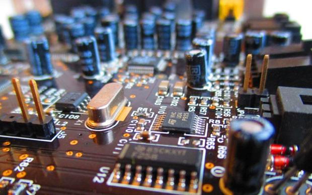
Identification of components
1.
Appearance recognition:
2.
1. resistorIdentify resistance values through color coding or directly printed numerical values.
2. capacitorThe marking may include capacitance value, withstand voltage level, and polarity (if it is an electrolytic capacitor).
3. diodeUsually there is a stripe marking the cathode.
4. transistorMark the model and pin configuration, please refer to the data manual for confirmation.
5. Integrated Circuit(IC)The model and pin direction are usually marked on the chip.
3.
Data manual:
4.
1. Search for the data manual of the component model to obtain detailed specifications and pin information.
Use of measuring instruments
Multimeter(Multimeter)
· Resistance measurementUsed to measure the resistance of resistors. Set the multimeter to resistance mode and connect it to both ends of the resistor.
· Voltage measurementUsed to measure the voltage between circuit points. Adjust to appropriate DC(DC or AC voltage range.
· Current measurementConnect in series to the circuit to measure current. Pay attention to selecting the appropriate current gear and ensure that the current limit of the multimeter is not exceeded.
· Connectivity testingCheck the connectivity in the circuit, the multimeter will beep if there are two electrical connections.
Oscilloscope(Oscilloscope)
· Observation of signal waveformUsed to observe dynamic waveforms of circuits, such as sine waves, square waves, etc.
· frequency measurement Measure the frequency and period of the signal.
· Amplitude measurementMeasure the peak of the signal-Peak value (Vpp) or other relevant voltage levels.
LCR table
· Inductance(L)、 Measurement of capacitance (C) and resistance (R)Specially designed for measuring inductors, capacitors, and more accurate resistance values.
· Quality factor(Q) Measurement of dissipation factor (D)Used to evaluate the performance of inductors and capacitors.
Precautions for use
1. safety firstBefore connecting any power or signal, ensure that the instrument is properly set up.
2. calibrationRegularly calibrate measuring instruments to maintain measurement accuracy.
3. Anti static electricityWhen handling sensitive components, use anti-static measures such as anti-static wristbands.
4. Connect correctlyEnsure that all connections are correct and error free to avoid short circuits or incorrect measurement results.
5. Document RecordRecord important data and observations during the measurement process for analysis and fault diagnosis.
By mastering the identification of electronic components and the correct use of measuring instruments, effective design, manufacturing, and maintenance of electronic devices can be carried out.


