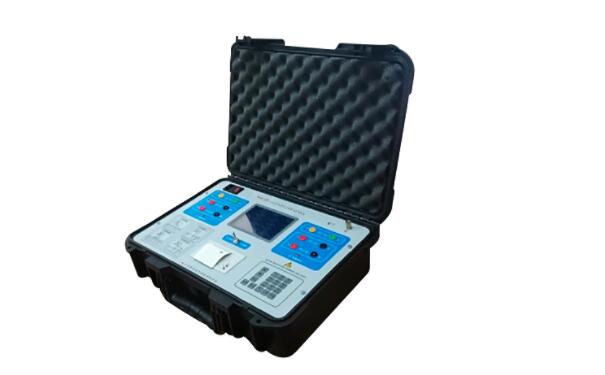
Contact resistance test - electrical performance test
Date:2021-10-29 15:23:00 Views:7581
catalogue
| summary | Action principle | influence factor |
| Standard requirements | Test content | Method steps |
| Typical method | objective | explain |
Introduction to contact resistance test
Contact resistance test, also known as ductor test, measures the resistance of electrical connections - terminals, connectors, connectors, bus sections or cable connections, etc. Such measurements are made on components such as connectors, relays and switches. Contact resistance test can understand the connection quality and conductive characteristics of the line, so as to avoid dangerous overheating of the contact.
Action principle of contact resistance
Observe the surface of the connector contact under the microscope. Although the gold plating layer is very smooth, the convex part of 5-10 microns can still be observed. You can see that the contact of a pair of inserted contacts is not the contact of the whole contact surface, but the contact of some points scattered on the contact surface. The actual contact surface must be smaller than the theoretical contact surface. According to the degree of surface smoothness and contact pressure, the gap between them can reach thousands of times. The actual contact surface can be divided into two parts; One is the direct contact part between real metal and metal. That is, contact point with no transition resistance between metals, also known as contact spots, is formed by contact pressure or thermal action which destroys the boundary film. The part accounts for about 5-10% of the actual contact area. The second is the parts contacting each other after polluting the film through the contact interface. Because any metal has a tendency to return to the original oxide state.
In fact, there is no really clean metal surface in the atmosphere. Even if the very clean metal surface is exposed to the atmosphere, it will quickly form an initial oxidation film of several microns. For example, an oxide film with a thickness of about 2 microns can be formed on the surface of copper in only 2-3 minutes, nickel in about 30 minutes and aluminum in only 2-3 seconds. Even for the particularly stable precious metal gold, due to its high surface energy, a layer of organic gas adsorption film will be formed on its surface. In addition, dust in the atmosphere will also form a deposited film on the surface of the contact. Therefore, from the microscopic analysis, any contact surface is a polluted surface.

Factors affecting contact resistance
1. Contact form
2. Contact pressure
3. Finish of contact surface
4. Stability of contact resistance in long-term operation
5. Temperature
6. Material properties
7. Use voltage and current
Contact resistance test requirements and standards
1. Test with 300V insulation resistance meter.
2. The contact resistance of the measured product should be less than 1q.
3. The test product shall be more than 5pcs.
Contact resistance test content
Two common inspections of circuit breaker contacts are visual inspection and contact resistance inspection.
1. Appearance inspection includes checking whether the contact of the circuit breaker is dented due to arc and contact wear or deformation.
2. The second inspection is contact resistance measurement. This involves injecting a fixed current through the contacts, usually about 100A, 200A and 300A, and measuring the voltage drop at both ends. The test is completed with a special contact resistance measuring instrument. Then, Ohm's law is used to calculate the resistance value. The resistance value needs to be compared with the value given by the manufacturer. This value should also be compared with previous records.
These two tests need to be completed together. Due to the fact that the contactor has good contact resistance but is still in a damaged state. Therefore, in order for the contactor to prove to be healthy, it needs to have good contact resistance and should be removed from the visual inspection test.
Contact resistance test method and steps
1. Test standard
The criteria for evaluating the contact resistance of electrical connections largely depend on the type of connection (e.g., bolted connection, welding, clamping, welding, etc.), metal contact surface area, contact pressure, etc. These vary from device to device. The manufacturer has no regulations or standards to specify the minimum contact resistance. Therefore, it is necessary to refer to the manufacturer's recommendations. For example, manufacturers sometimes cite a maximum contact resistance of 10 micro ohms for large bolted bus connections. Contact resistance measurement and its application fields are quite extensive.
2. Electrical connection
The electrical connection of the circuit has a variety of ways and means, such as welding, pressing, insertion and tight bonding. If you want to know the quality and conductivity of the connector, just measure its contact resistance. Contact resistance is usually used in the quality test of switches, relays and PCB pads.
In the aspect of mechanical components, the contact resistance of metal contact surface can be used to estimate the reliability and tightness of mechanical components. The contact resistance is related to the conductivity of the contact surface. The larger the area of the paired metal surface and the less impurities, the better the conductivity and the lower the resistance, and vice versa.
By measuring the contact resistance, we can qualitatively analyze the reliability and tightness of mechanical components. This technology has been used in the quality test of EMC shielding components. The measurement methods are different for different applications. For example, in the case of measuring the contact resistance of high-power switches and relays, a pair of contacts with high current should be used, just as it actually happens in the working state. For dry circuit connectors, the test current shall be low to prevent the connector from melting due to heat (current less than 100mA).
3. Mechanical assembly
When testing the quality of mechanical assembly, different test circuits should be selected according to different structures. There are two structures, closed-loop structure is closed and non closed-loop structure is open. Their measurement methods are completely different.
Typical methods of contact resistance test
Four wire (Kelvin) DC voltage drop is a typical method of micro ohmmeter for contact resistance test. More accurate measurement can be ensured by eliminating its own contact resistance and test lead resistance.
The contact resistance test uses two current connections for injection and two potential leads for voltage drop measurement; The voltage cable must be as close as possible to the connection to be tested and always in the circuit formed by the connected current leads.
From the measurement of voltage drop, the micro ohm controlled by the microprocessor calculates the contact resistance and eliminates the possible errors due to the thermal emf effect in the connection (thermoelectric EMF is the small thermocouple voltage generated when two different metals are connected together). They will be added to the measured total voltage drop, If they are not subtracted from the measurement by different methods (polarity reversal and averaging, direct measurement of Thermal EMF amplitude, etc.), they will introduce errors in the contact resistance test.
If a low resistance reading is obtained when testing the contact resistance of the circuit breaker with a low current, it is recommended to retest the contact with a higher current. Why do we benefit from higher currents? Higher currents will be able to overcome connection problems and oxidation on the terminals, where lower currents may produce erroneous (higher) readings under these conditions.
In contact resistance testing, it is important to maintain consistent measurement conditions and be able to compare with previous and future results of trend analysis. Therefore, when carrying out periodic measurements, the contact resistance test must be carried out at the same position, using the same test lead (always use the calibration cable provided by the manufacturer) and under the same conditions, so as to know when the bonding, connection, welding or equipment will become unsafe.
Purpose of contact resistance test
The contacts in the circuit breaker need to be checked regularly to ensure that the circuit breaker is healthy and functional. Poor contact or poor contact will lead to arc discharge, phase loss and even fire. This test is particularly important for contacts carrying large amounts of current, such as switchgear busbars, because higher contact resistance leads to lower ampacity and higher losses. The ductor test is usually performed using a micro / milliohmmeter or a low ohmmeter. The measurement of contact resistance is helpful to identify the fretting corrosion of contacts, and can diagnose and prevent contact corrosion. The increase of contact resistance will lead to high voltage drop in the system and need to be controlled.
Contact resistance test instructions
1. Qualified contact resistance test does not mean reliable contact. The test shows that only testing whether the static contact resistance is qualified can not guarantee the reliable contact under the dynamic bad environment.
2. Contact resistance is mainly affected by contact material, surface state and other factors.


 Weixin Service

 DouYin
 KuaiShou


