


 Weixin Service

 DouYin
 KuaiShou

Failure cause analysis of components and common fault detection methods
Date:2021-11-17 14:12:43 Views:4139
With the development of science and technology, especially the upgrading of electronic technology, the quality requirements of components used in electronic equipment are higher and higher. With the wide use of semiconductor devices, their life is degraded and eventually lead to failure. Failure analysis (FA) is a post inspection of failed devices. According to the needs, electrical testing and various advanced physical, metallographic and chemical analysis technologies are adopted, and the analysis is carried out in combination with the specific conditions before and after the failure of components and relevant technical documents, so as to verify the reported failure and determine the failure mode, failure mechanism and causes of the failure of components. Comprehensive and systematic failure analysis can determine the cause of failure, guide the improvement of device design, manufacturing process, test or application, and take corresponding corrective measures to eliminate the cause of failure mode or mechanism, so as to improve the overall reliability of devices and equipment.
Through failure analysis, the inherent quality problems of failed components can be found, and the service quality problems of components that fail because they are not used according to the specified conditions can also be found. Through feedback to relevant parties, the responsible party can be prompted to take corrective measures, so as to eliminate the causes of the reported failure mode or mechanism and prevent its recurrence, It plays a very important role in improving the inherent quality or service quality of components.
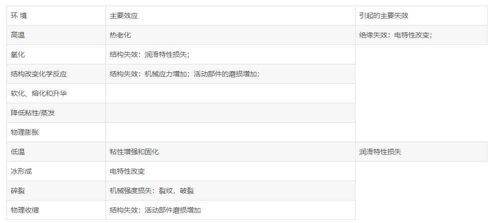
Failure due to temperature: one of the important factors of component failure is the influence of ambient temperature on components.
Effect of temperature change on semiconductor devices:
Because the forward voltage drop of p-n junction is greatly affected by temperature, the voltage transmission characteristics and anti-interference degree of bipolar semiconductor logic elements (integrated circuits such as TTL and HTL) composed of p-n as basic units are also closely related to temperature. When the temperature increases, the forward voltage drop of p-n junction decreases, and its opening and closing levels will decrease, which makes the low-level anti-interference voltage tolerance of the element decrease with the increase of temperature; The high-level anti-interference voltage tolerance increases with the increase of temperature, resulting in output level offset, waveform distortion, steady-state imbalance, and even thermal breakdown.
The p-n junction, the basic unit of bipolar semiconductor devices, is very sensitive to the change of temperature. When the p-n junction is reverse biased, the reverse leakage current formed by a few carriers is affected by the change of temperature. The relationship is as follows:
Where:

ICQ: reverse leakage current at temperature t0c
Icqr: reverse leakage current at temperature tr ℃
T-tr: absolute value of temperature change
It can be seen from the above formula that ICQ will double for every 10 ℃ increase in temperature. This will cause the working point of the transistor amplifier to drift, the transistor current amplification coefficient to change, the characteristic curve to change, and the dynamic range to become smaller.
✦ the relationship between temperature and allowable power consumption is as follows:
Where:
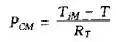
PCM: maximum allowable power consumption.
TJM: maximum allowable junction temperature.
T: Use ambient temperature.
RT: thermal resistance.
It can be seen from the above formula that the increase of temperature will reduce the maximum allowable power consumption of the transistor.
Effect of temperature change on resistance:
The effect of temperature change on resistance is mainly when the temperature rises. The increase of temperature will cause, for example, the increase of thermal noise of resistance, the deviation of resistance value from the nominal value, the decrease of allowable dissipation probability, etc. For example, when the temperature of carbon film resistance of RXT series rises to 100 ℃, the allowable dissipation probability is only 20% of the nominal value.
This characteristic of resistance is not only bad. For example, specially designed resistors: PTC (positive temperature coefficient thermistor) and NTC (negative temperature coefficient thermistor). Their resistance is greatly affected by temperature and can be used as sensors. For PTC, when its temperature rises to a certain threshold, its resistance will increase sharply. Using this characteristic, it can be used in the overcurrent protection circuit of the circuit board. When the current passing through it increases to its threshold current due to some fault, the temperature of PTC rises sharply. At the same time, its resistance value increases, limiting the current passing through it to protect the circuit. After troubleshooting, the current through it decreases, the temperature of PTC returns to normal, and its resistance value also returns to its normal value. For NTC, its characteristic is that its resistance decreases with the increase of temperature.
Effect of temperature change on capacitance:
The change of temperature will cause the change of capacitance to dielectric loss, which will affect its service life. When the temperature increases by 10 ℃, the service life of the capacitor decreases by 50%. At the same time, it also causes the change of resistance capacitance time constant, and even thermal breakdown due to excessive dielectric loss.
Failure due to humidity:One of the important factors of component failure is the influence of environmental humidity on components.
When the humidity is too high, when the dust containing acid and alkali falls on the circuit board, it will corrode the solder joint and wiring of components, resulting in solder joint falling off and joint fracture. High humidity is also the main cause of leakage coupling. Low humidity is easy to generate static electricity, so the humidity of the environment should be controlled at a reasonable level.
Failure due to high voltage:One of the important factors of component failure is the influence of high voltage on components.
The important condition to ensure the normal operation of components is to ensure the stability of the voltage applied to components. Too high voltage will increase the heat loss of components at least, and will cause electric breakdown of components at most. Take a capacitor for example, its failure rate is proportional to the 5th power of the voltage applied to both ends of the capacitor. For an integrated circuit, the voltage exceeding its maximum allowable voltage will cause direct damage to the device.
Voltage breakdown refers to that electronic devices have the highest withstand voltage value that can be borne. If it exceeds the allowable value, the device has the risk of failure. The failure modes of active components and passive components are slightly different, but there is also an upper limit of voltage. Transistor elements have withstand voltage values. Exceeding the withstand voltage value will damage the elements, such as diodes and capacitors. Exceeding the withstand voltage value of the elements will lead to their breakdown. If the energy is large, it will lead to thermal breakdown and the elements will be scrapped.
Failure caused by vibration and impact:One of the important factors of component failure is the influence of vibration and impact on components.
Mechanical vibration and impact will accelerate the failure of some internal defective components, resulting in catastrophic faults. Mechanical vibration will also loosen the welding points and crimping points, resulting in poor contact; If the vibration causes undue contact of the conductor, it will have some unexpected consequences.
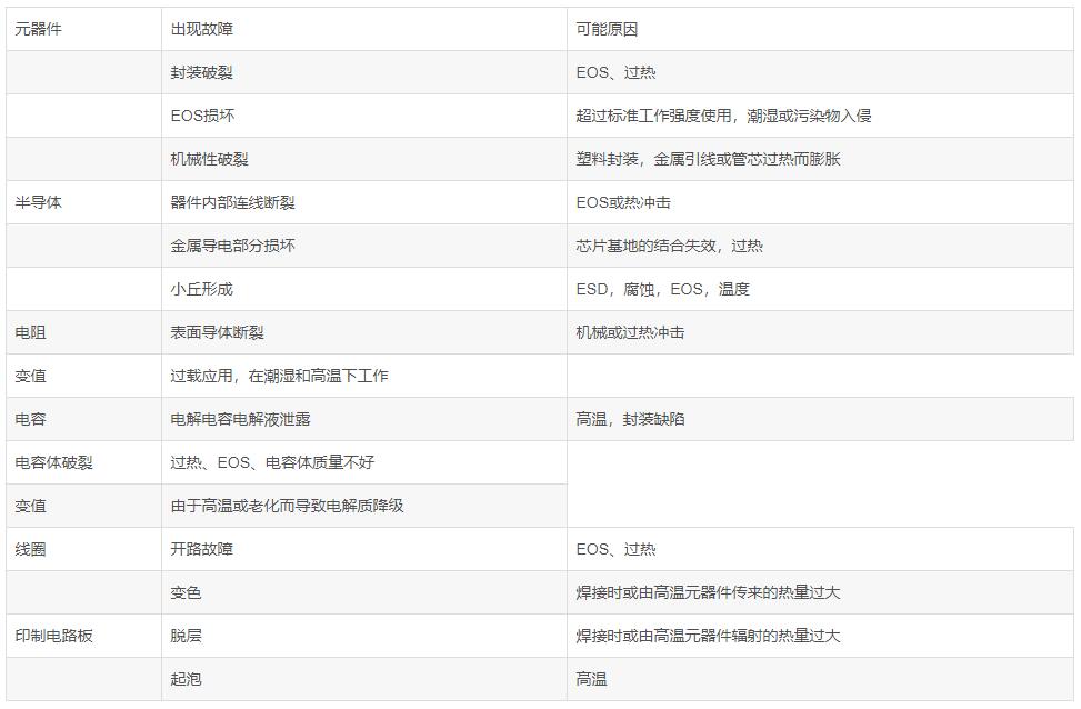
Possible failure modes and failure analysis:
✦ resistance failure analysis:
The failure mechanism of resistor potentiometer varies according to the type. The main failure modes of non-linear resistors and potentiometers are open circuit, resistance drift, lead mechanical damage and contact damage; The main failure modes of wire wound resistors and potentiometers are open circuit, lead mechanical damage and contact damage. There are four main categories:
●Carbon film resistor.Lead fracture, matrix defect, poor uniformity of film layer, groove defect of film layer, poor contact between film material and lead end, pollution between film and matrix, etc.
● metal film resistor.Uneven resistance film, broken resistance film, loose lead, decomposition of resistance film, silver migration, oxide reduction of resistance film, electrostatic charge, lead fracture, corona discharge, etc.
● wire wound resistor.Poor contact, current corrosion, loose lead, poor wire insulation, solder joint melting, etc.
● variable resistor.Poor contact, poor welding, broken contact * * or lead falling off, impurity pollution, poor epoxy adhesive, shaft inclination, etc.
The resistance is prone to deterioration and open circuit faults. After the resistance is deteriorated, the resistance value tends to drift. Generally, the resistance is not repaired, but directly replaced with a new resistance. Wire wound resistance when the resistance wire is burnt out, it can be used after welding again in some cases.
Resistance deterioration is mostly caused by poor heat dissipation, excessive humidity or defects during manufacturing, while burnout is caused by abnormal circuit, such as short circuit, overload and so on. There are two common phenomena of resistance burning out. One is that the over current causes the resistance to heat, causing the resistance to burn out. At this time, a burnt paste can be seen on the surface of the resistance, which is easy to find. In another case, the resistance is open circuit or the resistance value becomes larger due to the instantaneous high voltage added to the resistance. In this case, the resistance surface generally does not change significantly. The resistance of this fault phenomenon can often be found in high-voltage circuits.
Variable resistors or potentiometers are mainly wired and non wired. Their common failure modes are: parameter drift, open circuit, short circuit, poor contact, large dynamic noise, mechanical damage and so on. However, the actual data show that the main failure modes are quite different between laboratory test and field use. The majority of laboratory faults are parameter drift, while the majority of field faults are poor contact and open circuit.
The failure of poor contact of potentiometer is common in field use. For example, it accounts for 90% in telecommunication equipment and about 87% in television, so poor contact is a fatal weak link for potentiometer. The main causes of poor contact are as follows:
● the contact pressure is too small, * * stress relaxation, sliding contact deviates from the track or conductive layer, improper mechanical assembly, or contact * * deformation caused by large mechanical load (such as collision, drop, etc.).
● the conductive layer or contact track forms various non-conductive films at the contact due to oxidation and pollution.
● the conductive layer or resistance alloy wire is worn or burned, resulting in poor contact of the sliding point.
The open circuit failure of potentiometer is mainly caused by local overheating or mechanical damage. For example, the conductive layer or resistance alloy wire of the potentiometer is oxidized, corroded, polluted or overloaded due to improper process (such as uneven winding, uneven thickness of the conductive film, etc.), resulting in local overheating, burning out the potentiometer and open circuit; If the sliding contact surface is not smooth and the contact pressure is too large, the winding will be seriously worn and disconnected, resulting in open circuit; Improper selection and use of potentiometer, or failure of electronic equipment endangers the potentiometer and makes it work under overload or large load. These will accelerate the damage of potentiometer.
✦ capacitor failure analysis:
The common fault phenomena of capacitors mainly include breakdown, open circuit, degradation of electrical parameters, electrolyte leakage and mechanical damage. The main causes of these faults are as follows:
● breakdown。 There are defects, defects, impurities or conductive ions in the medium; Aging of media materials; Electrochemical breakdown of dielectric; Inter electrode edge arcing in high humidity or low pressure environment; Dielectric transient short circuit under mechanical stress; Metal ions migrate to form conductive channel or edge flashover discharge; Dielectric breakdown caused by air gap breakdown inside dielectric material; Mechanical damage of medium during manufacturing; The change of molecular structure of dielectric materials and the applied voltage higher than the rated value.
● open circuit。 Insulation of electrodes and leads caused by breakdown; The anode outgoing foil of electrolytic capacitor is corroded and broken (or mechanically broken); The low-level open circuit is caused by the oxide layer at the contact point between the outgoing line and the electrode; Poor contact or insulation between outgoing line and electrode; The metal foil from the anode of electrolytic capacitor leads to open circuit due to corrosion; Drying up or freezing of working electrolyte; Instantaneous open circuit between electrolyte and dielectric under mechanical stress.
● electrical parameter degradation。 Moisture and dielectric aging and thermal decomposition; Metal ion migration of electrode materials; Existence and change of residual stress; Surface contamination; Self healing effect of metallized electrode; Volatilization and thickening of working electrolyte; Electrolytic corrosion or chemical corrosion of electrodes; The contact resistance between lead and electrode increases; Effects of impurities and harmful ions.
Because the actual capacitor works under the comprehensive action of working stress and environmental stress, one or several failure modes and failure mechanisms will occur, and one failure mode will lead to the occurrence of other failure modes or failure mechanisms. For example, temperature stress can not only promote surface oxidation, accelerate the influence degree of aging and accelerate the degradation of electrical parameters, but also promote the decline of electric field strength and accelerate the early arrival of dielectric breakdown, and the influence degree of these stresses is a function of time. Therefore, the failure mechanism of capacitor is closely related to product type, material type, structural difference, manufacturing process, environmental conditions, working stress and other factors.
The breakdown fault of capacitor is very easy to find, but it is difficult to determine the specific fault component when there are multiple components in parallel. The determination of capacitor open circuit fault can be realized by paralleling the capacitor of the same model and capacity with the detected capacitor and observing whether the circuit function is restored. It is troublesome to check the change of capacitance electrical parameters, which can generally be carried out according to the following methods.
First, one of the leads of the capacitor shall be ironed off the circuit board to avoid the influence of surrounding components. Secondly, different methods are used to check the capacitor according to different conditions.
● inspection of electrolytic capacitor.Place the multimeter in the resistance gear, and the measuring range depends on the capacity and withstand voltage of the measured electrolytic capacitor. The measuring range of electrolytic capacitor with small capacity and high withstand voltage shall be located at R × 10kW block; Measure electrolytic capacitors with large capacity and low withstand voltage, and the measuring range shall be at R × 1 K W gear. Observe the charging current, the discharge time (the speed at which the gauge needle returns) and the last indicated resistance value of the gauge needle.
The identification methods of electrolytic capacitor quality are as follows:
① The charging current is large, the rising speed of the gauge needle is fast, the discharge time is long, and the return speed of the gauge needle is slow, indicating that the capacity is sufficient.
② The charging current is small, the rising speed of the gauge needle is slow, the discharge time is short, and the return speed of the gauge needle is fast, indicating small capacity and poor quality.
③ If the charging current is zero and the gauge needle does not move, it indicates that the electrolytic capacitor has failed.
④ At the end of the discharge, the resistance indicated by the meter needle when it returns to the end is large, indicating good insulation performance and low leakage.
⑤ At the end of the discharge, the resistance indicated at the end of the return of the meter needle is small, indicating poor insulation performance and serious leakage.
● general capacitor inspection with capacity above 1mf.The resistance gear (R) of the multimeter can be used × 10 kW) multiple measurements with the same polarity to check the degree of leakage and whether there is breakdown. Touch the two probes of the multimeter with the two leads of the measured capacitance and observe whether the probe swings slightly. For the capacitance with large capacity, the watch needle swings obviously; For capacitors with small capacity, the needle swing is not obvious. Then touch the lead of the capacitor again, three times and four times with the probe (the probes are not aligned). Observe whether the needle swings slightly each time. If the needle swings every time it touches from the second time, it indicates that there is leakage in the capacitor. If the gauge needle does not move when touching several times in succession, it indicates that the capacitor is good. If the gauge needle swings to the end point at the first collision, it indicates that the capacitor has been broken down. In addition, for capacitors with a capacity of 1mf ~ 20mf, some digital multimeter can measure.
● capacitor inspection with capacity less than 1 MF.The capacitance measuring gear of the digital multimeter can be used to measure the actual value of the capacitor more accurately. If there is no digital multimeter with capacitance measurement function, you can only use ohmic gear to check whether it has breakdown and short circuit. Use a good capacitor of the same capacity in parallel with the suspected capacitor and check whether it is open circuit.
● accurate measurement of capacitor parameters.LCR bridge can be used to accurately measure the capacity of a single capacitor, and transistor characteristic tester can be used to measure the withstand voltage value.
✦ failure analysis of inductance and transformer:
Such components include inductance, transformer, oscillation coil, filter coil, etc. The faults are mostly caused by external reasons. For example, when the load is short circuited, the current flowing through the coil exceeds the rated value and the transformer temperature rises, resulting in coil short circuit, open circuit or insulation breakdown. When the ventilation is poor, the temperature is too high or damp, electric leakage or insulation breakdown will also occur.
The common fault phenomena and causes of the transformer are as follows: when the transformer is powered on, if the iron core makes a buzzing sound, the fault cause may be that the iron core is not clamped or the transformer load is too heavy; If there is high heat, smoke, burning smell or fuse blown, the coil may be short circuited or overloaded.
The following methods are generally adopted for fault inspection of inductance and transformer components:
● DC resistance measurement method.Measure the quality of inductive components with the resistance block of multimeter. When measuring antenna coil and oscillation coil, the measuring range shall be set at the minimum resistance gear (such as R) × 1 W gear); When measuring the circumference and output input transformer, the measuring range shall be placed at the low barrier (R × 10W or R × 100 W gear), the measured resistance value is compared with the maintenance data or daily accumulated experience data. If it is very close, it indicates that the tested element is normal; If the resistance is much smaller than the empirical data, it indicates that the coil has a local short circuit; If the needle indicates zero, the coil is short circuited. It should be noted that the secondary resistance of oscillation coil, antenna coil and mid circumference is very small, only a few tenths of an ohm. Be especially careful when reading, and do not misjudge it as a short circuit. Block with high × 10kW) when measuring the resistance between the primary coil and the secondary coil, it should be infinite. If there is a certain resistance value between the primary and secondary, it indicates that there is leakage between the primary and secondary.
● power on inspection method.Power on the power transformer to check whether the secondary voltage drops. If the secondary voltage drops, it is suspected that there is a local short circuit in the secondary (or primary). When the transformer burns rapidly or has burning smell and smoke after power on, it can be judged that there must be a local short circuit in the transformer.
● instrument inspection method.The high frequency Q meter can be used to measure the inductance and its Q value, and the inductive short circuit instrument can also be used to judge the local short circuit of the low frequency coil. The megger can be used to measure the insulation resistance between the primary and secondary of the power transformer. If leakage is found in the transformer, it may be caused by poor insulation or moisture. At this time, the transformer can be removed to remove moisture and dry. In addition, various carbon brushes or copper brushes of the voltage regulating transformer are very easy to wear out in case of improper maintenance and use. Their fragments and carbon deposits often burn the transformer due to the burning of the coil of the short-circuit part. Therefore, attention should be paid to maintenance at ordinary times.


