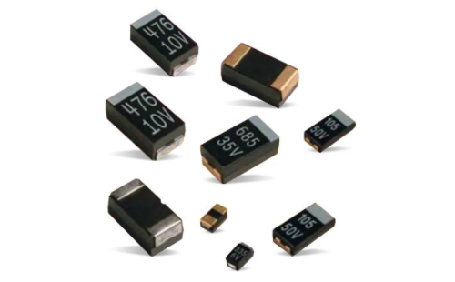
Summary of MLCC failure modes and analysis methods
Date:2022-02-15 18:19:42 Views:4617
Common IC failure modes: electrostatic damage, metal electromigration, chip bonding failure, over electric stress loss, metal fatigue, thermal stress, electromigration failure, physical damage failure, plastic packaging failure, lead bonding failure. When it comes to the causes of MLCC failure, under the normal use of the product, the root cause of failure is that there are various micro defects outside or inside the MLCC, such as cracking, holes, delamination and so on. These defects directly affect the electrical performance and reliability of MLCC products, and bring serious hidden dangers to product quality.

External factor: crack
1. Thermal crack
It is mainly caused by the temperature impact of the device during welding, especially wave soldering. Improper repair is also an important reason for the temperature impact crack.
2. Mechanical stress crack
The characteristic of MLCC is that it can bear large compressive stress, but its bending resistance is poor. Any operation that may produce bending deformation during device assembly may lead to device cracking. Common stress sources include: wafer alignment, circuit board operation in the process; Human, equipment, gravity and other factors in the process of circulation; Through hole component insertion; Circuit test and single board segmentation; Circuit board installation; Positioning riveting of circuit board; Screw installation, etc. This kind of crack generally originates from the upper and lower metallized ends of the device and extends to the inside of the device at an angle of 45 ℃. This kind of defect is also a type of defect that actually occurs most.
Internal factors: cavity, crack and delamination
1. Voids in ceramic media (voids)
The main factors leading to voids are organic or inorganic pollution in ceramic powder, improper control of sintering process and so on. The generation of voids can easily lead to leakage, which in turn leads to local heating inside the device, further reducing the insulation performance of ceramic media, resulting in increased leakage. The process of multi-layer capacitor combustion and even serious explosion will occur.
2. Sintering crack
Sintering cracks often originate from one end of the electrode and propagate along the vertical direction. The main reason is related to the cooling rate in the sintering process, and the cracks and hazards are similar to those of cavities.
3. Delamination
The sintering of multilayer ceramic capacitor (MLCC) is stacking and co firing of multilayer materials. The sintering temperature can be as high as 1000 ℃. Weak adhesion between layers, volatilization of internal pollutants in the sintering process and improper control of sintering process may lead to delamination. Delamination is similar to the damage of cavity and crack, which is an important internal defect of multilayer ceramic capacitor.
For external defects, manual visual inspection under microscope or automatic appearance sorting equipment are usually used. The internal micro defect has always been one of the difficulties in MLCC detection. It seriously affects the reliability of products, but it is difficult to find. Ultrasonic flaw detection method can more accurately detect the internal defects of MLCC, so as to select the defective products and improve the breakdown voltage and high voltage reliability of MLCC.
The characteristics of ultrasonic penetration and reflection (surface wave and bottom wave) are used to detect defects in objects. The use of ultrasonic flaw detector can accurately find out the internal micro defects of MLCC with defects, determine the location of defects, and conduct further grinding piece analysis. For the products with internal defects, the whole batch of scrapping treatment is adopted, which shows the effectiveness and reliability of ultrasonic flaw detection method in the detection and determination of MLCC internal defects.
Normal sample: the overall color of the sample scanning photo is green and yellow, indicating that the display of the sample body is normal. The appearance of red and blue on the edge of some samples is due to the uneven surface height of the edge of the sample, which is a normal phenomenon.
Abnormal sample: if the color of the sample body appears red and blue, the suspicious sample will be scanned and confirmed again.
Failure analysis method
01 electrical characteristic test: it is usually used in the preliminary stage of failure analysis. The purpose is to master the electrical parameters or functional failure status of the sample to facilitate preparation for further analysis.
02 observation and measurement: confirm the abnormal position and specific condition of IC by observing the external / internal appearance & structure of IC. Such tests are generally used in combination with DPA (destructive physical analysis).
03dpa destructive test: locate and present the specific failure position inside the IC through liquid erosion, mechanical damage, laser cutting and other damage methods.
04 reliability test: it is to verify the service life and performance stability of IC by using various environmental test equipment to simulate high temperature, low temperature, high temperature and high humidity and temperature change in climatic environment.
In conclusion, failure analysis is of great significance to the production and use of products. By analyzing the samples of process waste and defective products, early failure, test failure, pilot failure and field failure, confirm the failure mode, analyze the failure mechanism, clarify the failure causes, and finally give preventive countermeasures to reduce or avoid the recurrence of failure.


 Weixin Service

 DouYin
 KuaiShou


