


 Weixin Service

 DouYin
 KuaiShou

EMC testing technology and fault diagnosis method
Date:2022-04-19 14:00:00 Views:2783
Electromagnetic compatibility test EMC (electro magnetic compatibility) refers to the ability of equipment or system to meet the requirements in its electromagnetic environment and not produce intolerable electromagnetic interference to any equipment in its environment. EMC test includes two aspects: test the electromagnetic disturbance intensity sent to the outside world to confirm whether it meets the limit value requirements specified in relevant standards; The sensitivity test shall be conducted under the electromagnetic environmental conditions with specified electromagnetic disturbance intensity, so as to confirm whether it meets the immunity requirements specified in relevant standards. For engineers and technicians engaged in the design of single chip microcomputer application system, it is very necessary to master a certain EMC test technology. EMC is the abbreviation of electro-magnetic compatibility, which includes electromagnetic interference (EMI) and electromagnetic sensitivity (EMS). Because electrical products have electromagnetic interference to other electrical appliances or are subject to electromagnetic interference from other electrical appliances, it is not only related to the reliability and safety of products, but also may affect the normal work of other electrical appliances, and even lead to safety hazards.
1. EMC test of single chip microcomputer system
(1) Test environment
In order to ensure the accuracy and reliability of the test results, EMC measurement has high requirements for the test environment. The measurement sites include outdoor open space, shielding room or anechoic chamber.
(2) Test equipment
EMC measuring equipment is divided into two categories: one is electromagnetic interference measuring equipment, which can measure electromagnetic interference when connected with appropriate sensors; The other is in electromagnetic sensitivity measurement. The equipment simulates different interference sources and applies them to all kinds of tested equipment through appropriate coupling / decoupling networks, sensors or antennas for sensitivity or interference measurement.
(3) Measurement method
According to different standards, there are many measurement methods for EMC test, but they can be divided into four categories; Conducted emission test, radiated emission test, conducted sensitivity (immunity) test and radiated sensitivity (immunity) test.
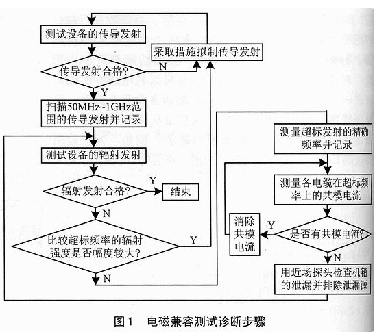
(4) Test diagnostic procedure
Figure 1 shows the electromagnetic interference emission and fault analysis steps of an equipment or system. Following this step can improve the efficiency of test and diagnosis.
(5) Test preparation
① Test site conditions: EMC test laboratory is radio wave semi anechoic chamber and shielding chamber. The former is used for radiation emission and radiation sensitivity test, and the latter is used for conducted emission and conducted sensitivity test.
② Environmental level requirements: the electromagnetic environmental level of conduction and radiation should be far lower than the limit value specified in the standard. Generally, the environmental level should be at least 6dB lower than the limit value.
③ Test table.
④ Isolation of measuring equipment and tested equipment.
⑤ Sensitivity criterion: it is generally provided by the tested party, monitored and judged truthfully, and the degree of performance degradation is determined by measurement and observation.
⑥ Placement of tested equipment: in order to ensure the repeatability of the experiment, there are usually specific provisions on the placement of tested equipment.
(6) Test type
Conducted emission test, radiated emission test, conducted immunity test, radiated immunity test.
(7) Common measuring instrument
Electromagnetic interference (EMI) and electromagnetic sensitivity (EMS) testing requires many electronic instruments, such as spectrum analyzer, electromagnetic interference measuring instrument, signal source, functional amplifier, oscilloscope and so on. Because the EMC test frequency is very wide (20Hz ~ 40GHz) and the amplitude is very large( μ Class V to kW), many modes (FM, am, etc.) and many postures (flat, oblique, etc.), so it is very important to use electronic instruments correctly. A suitable instrument for measuring electromagnetic interference is a spectrum analyzer. Spectrum analyzer is an instrument that displays the law of voltage amplitude changing with frequency. The waveform it displays is called spectrum. The spectrum analyzer overcomes the shortcomings of the oscilloscope in measuring electromagnetic interference, and can accurately measure the interference intensity at each frequency. The spectrum analyzer can directly display each spectrum component of the signal.
When solving the problem of electromagnetic interference, the most important problem is to judge the source of interference. Only after accurately locating the interference source can we put forward the measures to solve the interference. Determining the interference source according to the frequency of the signal is the simplest method, because among all the characteristics of the signal, the frequency characteristic is the most stable, and people often know the signal frequency of each part of the circuit very well. Therefore, as long as we know the frequency of the interference signal, we can infer which part of the interference is generated. For the electromagnetic interference signal, because its amplitude is often much smaller than the normal working signal, it is very simple to use the spectrum analyzer to make this measurement. Due to the narrow if bandwidth of the spectrum analyzer, it can filter out the signals different from the interference signal frequency, accurately measure the interference signal frequency, and judge the circuit generating the interference signal.
2. EMC troubleshooting Technology
(1) Solution of conduction problem
① Reduce EMI current by connecting a high impedance in series.
② Short circuit EMI current to ground or other loop conductors by paralleling a low impedance.
③ Cut off EMI current through current isolation device.
④ Restrain EMI current through its own action.
(2) EMC capacitive solutions
A common phenomenon is that one side of the filter capacitor is not directly connected with a separate impedance, but with the transmission line. Typically, when the length of an input / output line reaches or exceeds 1 / 4 wavelength, the transmission line becomes "long". In fact, this change can be approximated by the following formula:
l≥55/f
Where: l unit is m and F unit is MHz. This formula takes into account the average propagation velocity, which is 0.75 times that of free space theory.
a. Dielectric materials and tolerances
Most of the capacitors used in EMI filtering are non-polar capacitors.
b. Differential mode (line to line) filter capacitive capacitance.
c. Common mode (line to ground / enclosure) filter capacitor
Common mode (CM) decoupling usually uses a small capacitor (10 ~ 100nF). The small capacitor can short circuit the undesired high-frequency current to the housing before it enters the sensitive circuit or when it is far away from the noise circuit. In order to obtain a good high-frequency attenuation circuit, reducing or eliminating parasitic inductance is the key. Therefore, it is necessary to use ultra short wires, especially leadless components.
(3) Inductive and series loss EMC solutions
In terms of capacitance, if ZS and Z1 are not pure resistors, their actual values should be used when calculating the frequency. When the capacitor is connected in series in the power supply or signal circuit, it must meet the following requirements:
① The working current flowing shall not cause the inductance to overheat or be too large, which will lead to excessive voltage drop;
② The current flowing through can not cause inductive magnetic saturation, especially for high magnetic conductivity materials.
There are several solutions:
*Magnetic core material;
*Ferrite and ferrite loaded cables;
*Inductance, differential mode and common mode;
*Grounding choke;
*Combined inductor capacitor element.
(4) Solution of radiation problems
In many cases, the problem of radiated electromagnetic interference may arise and be eliminated in the conduction stage. Some solutions can inhibit the interference device from working on the radiation transmission channel like field shielding. According to the shielding theory, the shielding effect mainly depends on the frequency of the electromagnetic interference source, the distance from the shielding device and the characteristics of the electromagnetic interference field - electric field, magnetic field or plane wave.
① Conductor tape. Use copper or aluminum strip to simply and quickly establish a direct shielded and low resistance connection or bus. They are convenient for temporary solutions and relatively permanent solutions. The thickness is between 0.035 ~ 0.1mm, and the back is equipped with conductive adhesive for installation. If copper conductive tape is used, its passing resistance is about 20m Ω / cm2. Application: electrical shield; Location of leakage point in case of failure; As an emergency solution, turn plastic into metal and shield ordinary flat cables.
② Mesh shielding tape and zipper jacket. Tin coated steel mesh belt: it is mainly used to install on an assembled electricity tariff sheath as an easy to install bandage type shielding cover. In order to reduce the magnetic field radiation or sensitivity of electricity charges, steel mesh belt is an effective solution.
Zipper shield jacket: used when there are obvious signs that electricity charge is the main cause of EMI coupling.
③ EMI gasket. Application: when the following conditions exist and real se is required, EMI gasket is the most commonly used method to solve radiation problems, sensitive problems, ESD, electromagnetic pulse and tempest problems.
*Chassis leakage has been identified as the main radiation path.
*The mating surface is not smooth, flat or hard enough to provide good connection contact by itself.
④ EMI shielding of windows and ventilation panels: suitable for shielding of aperture.
The approximate model of plane wave is:
SE≈104(-20-lgl)-20lgf
Where, se is in db; L is the size of grid or mesh, in mm; F is in MHz. Of course, as the frequency decreases, the upper limit of the shielding efficiency se of the mesh is limited by the metal itself. In the near field, the shielding power she of the H field is not affected by the frequency, which can be approximated by the following formula:
SEH≈10lg(πr/l)
Where, R is the distance from the source to the shield, and l is the mesh size, both in mm.
⑤ Conductive coating: it is applied to establish EMI shielding cover on the plastic shell of the system, send the shielding efficiency se of the existing ordinary or deteriorated conductive surface, prevent ESD or electrostatic accumulation, and increase the contact area of the joint surface or sealing gasket.
⑥ Conductive foil: aluminum is a good conductor. It has no absorption loss below 10MHz, but it has good reflection loss for any frequency of electric field. For applications, please refer to relevant materials.
⑦ Conductive cloth: it can be used in any three-dimensional shielding occasions where the frequency range from 100kHz to GHz needs to reach 30 ~ 30dB attenuation.
3. Application of new EMC devices and materials
3.1 power line filter
The power line filter is installed between the power line and electronic equipment to simulate the parasitic electromagnetic interference in power transmission, which plays an important role in improving the reliability of the equipment. The filter allows some frequencies to pass through, while the components of other frequencies are simulated. According to the characteristics of the interference source, frequency range, voltage, impedance and other parameters and the requirements of load characteristics, the filter shall be selected appropriately.
3.2 signal blocking transformer
Pulse type (digital or thyristor gate driven) or analog isolation transformer and the isolation transformer used in AC power supply have the same principle as the isolation transformer used in AC power supply, but the transmission frequency band is completely different. Some performance requirements of the transformer (such as distortion, 3dB bandwidth, loss, symmetry, impedance, pulse delay, etc.) are very strict for useful signal processing. This kind of transformer belongs to broadband equipment, and the ratio of the highest frequency to the lowest frequency Fmax / Fmin reaches tens of times. By cutting off the common mode ground loop at the transmitter or receiver, the isolation transformer can simulate the common mode noise without changing the differential mode signal. Since the common mode voltage is added on both sides of the primary and secondary sides of the transformer, this isolator must have a high breakdown voltage: the typical value is 1.5kV, and in some cases it is as high as 10kV.
The main advantages of signal transformer are its simplicity, durability, durability, linearity and moderate price. When the frequency increases, its electromagnetic compatibility performance decreases.
Application:
*When loop isolation is required, its frequency range is from DC to tens of MHz;
*When the analog voltage is less than or equal to 10mV and the common mode signal is less than or equal to 10mV;
*In the thyristor application circuit, the trigger is isolated from the common mode voltage;
*As a field solution, it can be used to cut off a ground loop and build a balanced or unbalanced transmission line.
3.3 power isolation transformer, power regulator and uninterruptible power supply
(1) Power isolation transformer
The common isolation transformer can cut off the grounding loop of the main power line in the low frequency range. When the frequency increases, the electrical isolation decreases due to the existence of the primary side inter storage capacitance C1-2. In order to reduce the influence of parasitic capacitance, the primary and secondary windings of drop system, spiral and split type can be used, which can reduce the parasitic capacitance to 1 / 3 ~ / 10 of the original.
(2) Faraday shielded transformer
A layer of aluminum foil or copper foil is wrapped between the primary and secondary coils and kept out of contact with the coil to avoid short circuit. Faraday shield or electrostatic shield is grounded. The scope of application is as follows:
*Applied to indoor power supply or power distribution box, as a simple 1:1 isolation transformer to isolate 50 / 60Hz ground loop;
*Regenerate the AC power supply that remains neutral to the ground in a part of the same system and keep it electrically isolated from the main power distribution point;
*It is applied to prevent the transition from frequently triggering the ground fault detector in the system when there is a large earth leakage current in the system;
*It can be used in combination with power line filter. The attenuation characteristics of power line filter only start at tens or hundreds of kHz.
3.4 transient suppressor
Rheostat and solid-state rheostat (transzorbs) are components with nonlinear V-I characteristic curve, which can be used as voltage stabilizing components. When the voltage passes through the device, it is clamped at a voltage equal to or greater than the breakdown voltage VBR. The response speed of the device is fast, but there is a certain limit on the processing energy value.
3.5 lapping, ground continuity and RF impedance reduction devices
① The grounding braid or flat conductor with metal bandwidth has less inductance than the circular conductor with the same cross section. As a preferred selection reference, you can use:
*Flat metal strip;
*Flat braid with flat grounding terminal;
*Jumpers for round, stranded wires.
② Printed circuit board (PCB) grounding gasket. In order to build a more direct low resistance EMI current receiver, a grounding gasket needs to be used. Usually, there is a spring clip in the middle of the resin gasket to provide strong and reliable pressure on the OV copper plate on one side and the mounting chassis with PCB on the other side. As the spring is made of copper tin material, it has good electrical contact performance, and the contact resistance is in the order of M Ω.
③ Metal tariff trunking and its metal braided layer. The function of metal cable tray, common conductor and metal braid is to transmit partial grounding circulation between several interconnected equipment. It can be regarded as a common mode short circuit channel between different chassis or ground wires, but in fact, this method can not be applied to a long distance except DC or AC 50 / 60Hz; It can be used in computer rooms, factory workshops or other large sites with many unshielded electricity charges. It is impossible or difficult to replace them with shielded electricity charges or put them into pipelines.
④ The ground impedance is reduced and the grounded pad of the raised metal base plate. In order to reduce the input of conducted transient interference and the impact of surrounding RF field on the system, it can be improved by setting indoor reference grounding plate or grounding network. Through this method, it is easy to achieve 20dB improvement at frequencies up to hundreds of MHz, and it is also possible to reduce the ground potential deviation between different equipment in the same room.
Another technology: indoor, it is recommended to install raised metal base plate (RMF), and use the reinforcement of floor tile as the grounding reference grid; By replacing plastic damping gasket with conductive damping gasket, a good and lasting electrical connection can be established.
② Temporary grounding plate. This latter solution was originally used by IBM's installation planning engineers, that is, to install a copper plate or electroplated steel plate. For those occasions without "actual ground", due to the large capacitance (300 ~ 1000pf) between the temporary grounding plate and the special structure of the building, it provides a more effective absorption device for the Faraday shielding layer of electromagnetic interference filter, transient protector and isolation transformer. At the high frequency end, this virtual ground is more effective than a long, green or yellow green grounding conductor.
In the actual EMC test application, in addition to passing the identification test of the standard qualification laboratory, there are two feasible methods also recognized by the industry: TCF (technical construction file) and self certification. Anti interference ability test is a very practical test item. The best way to realize electromagnetic compatibility is to treat all digital and analog circuits as circuits that respond to high-frequency signals, and use high-frequency design methods to deal with electricity shielding, PCB wiring and common mode filtering. It is also important to use the whole ground plane and power plane, as well as the analog circuit, which is conducive to limiting the high-frequency common mode ring. Most transient disturbances belong to high frequency and produce strong radiation energy.


