


 Weixin Service

 DouYin
 KuaiShou

Focusing on details and using failure analysis to identify the root cause of production problems
Date:2023-09-21 17:26:00 Views:3013
introduction
Electronic component failure refers to the complete or partial loss of function, parameter drift, or intermittent occurrence of the above situations. Electronic component analysis is a post inspection of failed components. As needed, use electrical testing and necessary physical, metallographic, and chemical analysis techniques to verify the reported failures, confirm their failure modes, and identify the failure mechanisms.
The main analysis objects include semiconductor discrete devices such as resistors, capacitors, inductors, connectors, MOS, relays, diodes, transistors, thyristors, integrated circuits of various scales and packaging forms, RF and microwave devices, power modules, optoelectronic modules, and other components and modules.
1、 Case Background
The customer has a batch of inventory chips that have already been sold. When the buyer uses this batch of chips for production operations, the PL-2 experiences power failure, flameout, no light, or button failure, and the defect rate is as high as 60%. In order to identify the problem, a fixture was used to test the PCB board, and it was found that some parts needed to be powered off 4-6 times before this phenomenon occurred.
Next, the buyer removed the microcontroller from the functioning PCB component and replaced it with the defective PCB component, restoring the functionality of the PCB component to normal.
The IC that was removed from the defective PCB component and the program for re burning is still NG, suggesting a quality issue with the microcontroller.
Therefore, the buyer returned the batch of products, and the customer entrusted us to assist in analyzing the cause of the defect in order to confirm whether it was caused by the chip itself.
2、 Analysis process
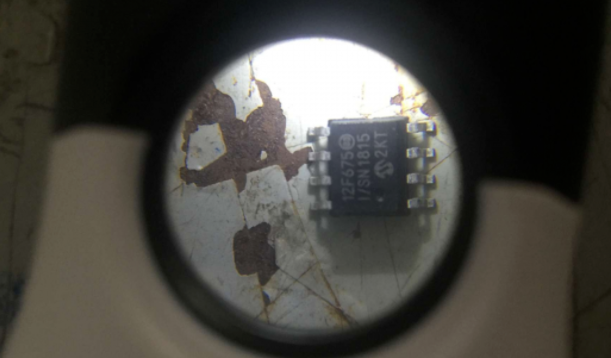
▶ 1. Appearance analysis
Conduct visual inspection on the failed samples provided by the client to confirm whether there are obvious abnormal issues on their surface
Test results: From the appearance of the defective sample, no damage was found, and no issues such as screen printing ghosting or blurring were found on the microcontroller.
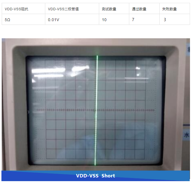
▶ 2. Electrical characteristic testing
In order to confirm the failure mode of the failed sample and check if there are any abnormal issues such as open circuit, short circuit, impedance, etc., electrical characteristic testing was conducted on the sample
Test results: A total of 10 defective products were tested during the electrical characteristic test, among which 3 pieces of pin1 VDD were found to have a short circuit to pin8 VSS
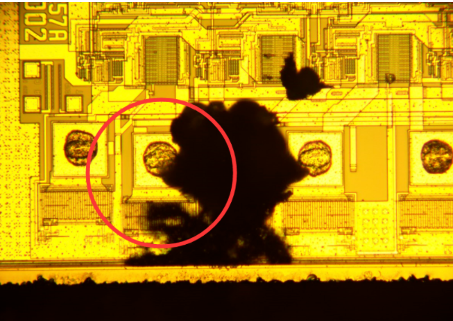
▶ 3. Cover opening inspection
In order to confirm whether there are obvious abnormalities inside the sample, an open cover test was conducted on the sample
Test results: Cover opening inspection found burn marks on the internal wafer of the chip
3、 Comprehensive analysis
After visual inspection, electrical characteristic testing, and cover opening inspection, it was found that:
(1) Impedance short circuit between defective product measurement VDD and VSS
(2) Cover opening inspection, wiring and packaging are normal
(3) EOS damage found on the surface of the uncovered wafer
▶ Knowledge sharing: EOS/ESD damage principles
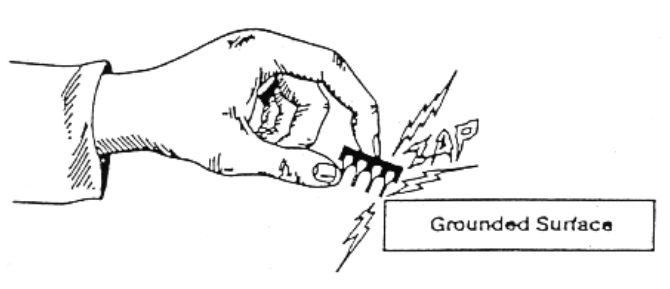
When it comes to the principle of EOS/ESD damage, it is necessary to mention ESD in human discharge mode and ESD in machine discharge mode. We need to have a clear understanding of these two modes.
The Human Body Discharge Mode (HBM) ESD refers to the accumulation of static electricity on the human body due to friction or other factors when walking on the ground. When the person touches the IC, the static electricity on the human body will enter the IC through the pin (PIN) of the IC, and then discharge to the end (GROUP) through the IC, as shown in the figure below.
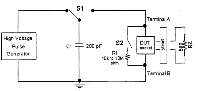
Machine discharge mode (ESD) refers to the accumulation of static electricity by the machine itself (such as a robotic arm, test fixture, hand tool, etc.). When the machine touches the IC, the static electricity is discharged through the PIN of the IC. Because most machines are made of metal, the equivalent resistance of their machine discharge mode is 0 Ω, and their equivalent capacitance is set at 200PF. Due to the equivalent resistance of the machine discharge mode being 02, the discharge process is shorter, with several amperes of instantaneous discharge current generated within a few nanoseconds to tens of nanoseconds.
When excessive current passes through the internal circuit of the IC, it is easy to cause damage to the internal circuit and affect the overall function of the IC.
Generally, there is an ESD protection circuit in the design of IC circuits. If the machine's ESD is not properly prepared or if peripheral circuits, software upgrades, circuit designs, etc. are not completed before starting the computer, it can cause EOS/ESD to instantly generate current and cause damage to the internal circuit of the chip.
4、 Conclusion and suggestions
▶ 1. Conclusion
No defects were found in 100 confirmed inventory samples, and the products meet the original factory specifications.
▶ 2. Suggestions
Check the relevant circuits and equipment for leakage or other causes of production defects, and confirm whether the customer's relevant testing personnel have taken appropriate anti-static measures.


