IGBT Short Circuit Testing: A Deep Analysis of Principles and Guidelines for Experimental Methods
Date:2024-03-07 16:23:26 Views:4756
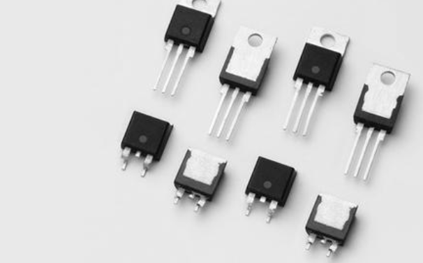
IGBT (Insulated Gate Bipolar Transistor) is a commonly used power semiconductor device with advantages such as fast switching speed and low loss. It is widely used in industries, transportation, medical and other fields. However, IGBT may experience short circuit faults during use, seriously affecting the normal operation of the equipment. Therefore, conducting short-circuit testing on IGBTs is essential. This article will deeply analyze the principle of IGBT short-circuit testing and provide experimental method guidelines to help readers better understand and master this important testing technology.
1、 The significance of IGBT short circuit testing
IGBT short circuit testing is indispensable in evaluating device performance. Through short-circuit testing, it is possible to accurately evaluate the working status, tolerance, and effectiveness of protection mechanisms of equipment under short-circuit conditions.
The core objective of short circuit testing is to determine two common types of short circuits: intra arm short circuits and inter arm short circuits. Only by fully understanding these types of short circuits and their characteristics can targeted protection measures be designed to improve the reliability and safety of the system.

2、 Short circuit test inside the bridge arm
Short circuit within the bridge arm (through) is a hardware or software failure that results in a small inductance (100nH) in the short-circuit circuit. The commonly used short circuit protection method is to use VCE (sat) detection.
Schematic diagram of short circuit test inside the bridge arm: The voltage of the bus capacitor is charged to the required value through a voltage regulator and contactor. After closing the gate of the upper tube IGBT, a thick and short copper bar is used for short circuit, and then a single pulse is released on the lower tube IGBT to form a straight through state.
Precautions for short circuit testing within the bridge arm:
Special attention should be paid to the influence of the length and thickness of the short-circuit bar on the measurement results;
Ensure that the energy required for short-circuit testing comes from the busbar capacitor bank;
The upper IGBT is always in the off state, but its diode plays an important role in short-circuit current continuation;
The test requires measuring the three physical quantities of Vce, Vge, and Ic in the lower tube;
Pay attention to selecting the correct position of the current probe to obtain accurate current waveforms.
3、 Short circuit test between bridge arms
Short circuit between bridge arms is caused by phase to phase or phase to ground short circuit, and the inductance in the short circuit circuit circuit is relatively high (uH level). Short circuit protection can be achieved through VCE (sat) detection or Hall detection of current changes.
In the short circuit test between bridge arms, the inductance is uncertain and requires flexible application of different protection methods, combined with specific situations for analysis and experimentation.
4、 Short circuit test experimental steps
Determine the width of a single pulse: Under low voltage conditions, confirm the width of the emitted single pulse to prepare for subsequent experiments.
Send a single pulse for preliminary confirmation: adjust the bus voltage to 20-30V, send a single pulse to confirm the accuracy of the current probe direction and physical quantity measurement, as well as the oscilloscope capture ability.
Adjust the bus voltage: Adjust the bus voltage to the rated value, disconnect the incoming contactor, and send a single pulse to confirm that the oscilloscope can correctly capture the moment.
Appropriate bus voltage setting: The bus voltage should be adjusted appropriately to avoid strange oscillation phenomena. For different specifications of IGBTs, a reasonable bus voltage should be set according to the specific situation.
Pay attention to short-circuit current and Vce voltage: observe the maximum value of short-circuit current and compare it with the values in the specification book to determine whether it is too high or if there is a problem of current oscillation. At the same time, pay attention to the Vce voltage and control it within 10 microseconds from the timing of de saturation to the time when the current is turned off.
Pay attention to gate clamp circuits: Gate clamp circuits have a significant impact on the peak short-circuit current and require special attention to their performance to ensure safety.
Pay attention to environmental temperature: Environmental temperature has a significant impact on the experimental results, and the appropriate temperature should be selected according to the system specifications to carry out the experiment.
5、 Analysis of experimental results
The total inductance in the short-circuit circuit can be calculated by the current rise rate di/dt, and the previously measured stray inductance can be subtracted to obtain the inductance inserted into the copper bar.
Pay attention to the peak value of short-circuit current and determine if it is too high and if there is any current oscillation phenomenon.
Observe the time required for de saturation and the peak height of Vce voltage at shutdown to determine if there is any danger, and verify whether the active clamp is working properly.
The evaluation of gate voltage needs to be cautious, as both di/dt and du/dt are large during testing, and gate probes can easily cause inaccurate measurements.
IGBT short circuit testing is an important means to ensure the normal operation of equipment. This article provides an in-depth analysis of its principle and provides experimental method guidelines. In practical operation, we should pay attention to the correct execution of testing steps and further analyze and optimize based on experimental results to ensure the stable and reliable operation of IGBT under short circuit conditions. Only through sufficient short-circuit testing can we better ensure the operational effectiveness of power equipment and the safety of personnel.


 Weixin Service

 DouYin
 KuaiShou


