


 Weixin Service

 DouYin
 KuaiShou

Identification and detection of crystal diodes for electronic components
Date:2021-04-26 17:52:00 Views:5443
Diode is called crystal diode, which is a kind of semiconductor device, also known as semiconductor diode. The structure of crystal diode is a p-n junction structure formed by p-type nodule semiconductor and n-type nodule semiconductor. Respective space charge layers are formed on both sides of the nodule, and the equivalent of self built electric field is built. If there is no applied voltage, due to p-n The diffusion current caused by the carrier concentration difference on both sides of the junction is equal to the drift current caused by the self built electric field.
Diode identification
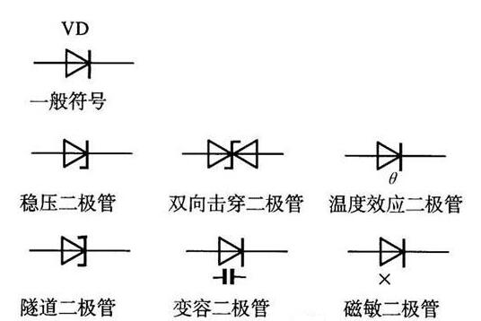
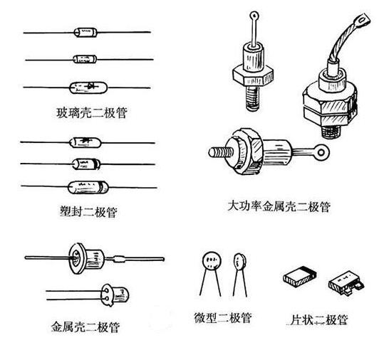
The identification of diodes is very simple. The N-pole (negative pole) of low-power diodes is mostly marked with a color circle on the outside of the diodes. Some diodes also use special symbols for diodes to represent P-pole (positive pole) or N-pole (negative pole), and some use symbols "P" and "n" to determine the polarity of diodes. The positive and negative poles of the LED can be identified from the length of the pin. The long pin is positive and the short pin is negative.
Function of diode
The main characteristic of diode is unidirectional conductivity, that is, the on resistance is very small under the action of forward voltage; Under the action of reverse voltage, the on resistance is very large or infinite. Because the diode has the above characteristics, it is often used in circuits such as rectification, isolation, voltage stabilization, polarity protection, coding control, FM modulation and squelch in cordless telephones. The crystal diodes used in the telephone can be divided into rectifier diodes (such as 1N4004), isolation diodes (such as 1N4148), Schottky diodes (such as BAT85), light emitting diodes, voltage stabilizing diodes, etc.
Diode detection
Turn the multimeter to the buzzer diode gear, the red pen is connected to the positive pole of the diode, and the black pen is connected to the negative pole of the diode. At this time, the forward conduction resistance of the diode, that is, the forward voltage drop of the diode, is measured. Different diodes have different forward voltage drop values according to their internal materials.
The reading of forward voltage drop value is normal when it is 300-800. If it is 0, it indicates diode short circuit or breakdown. If it is 1, it indicates diode open circuit. Change the probe and measure again. The reading should be 1, i.e. infinity. If it is not 1, the diode is damaged When the forward voltage drop is about 200, it is a zener diode; Both readings of the fast recovery diode are about 200, which is normal. When measuring the voltage stabilizing diode, the voltage stabilizing value of the voltage stabilizing tube we usually use is generally greater than 1.5V, while the R of the pointer meter × The resistance gear below 1K is powered by the 1.5V battery in the meter. In this way, use R × The voltage stabilizing tube with resistance below 1K has complete unidirectional conductivity just like the measuring diode. But the R of the pointer table × 10K gear is powered by 9V or 15V battery, and R is in use × 10K, when measuring the voltage stabilizing tube whose voltage stabilizing value is less than 9V or 15V, the reverse resistance value will not be ∞, but there is a certain resistance value, but this resistance value is still much higher than the forward resistance value of the voltage stabilizing tube. In this way, we can preliminarily estimate the quality of the regulator.
Inspection precautions
When using a digital multimeter to support and measure the diode, the red probe is connected to the positive pole of the diode and the black probe is connected to the negative pole of the diode. At this time, the measured resistance is the positive conduction resistance of the diode, which is just opposite to the probe connection method of the pointer multimeter.


