Experience sharing of electronic component testing: how to judge the quality of various diodes
Date:2021-05-11 14:06:26 Views:4334
Diode faults are mainly manifested in open circuit, short circuit and unstable voltage stabilization. Among the three faults, the former one shows the increase of power supply voltage; The latter fault shows that the power supply voltage becomes low to zero volts or the output is unstable. How to check and judge the diode? Below, Chuangxin online testing organization will share the testing experience of electronic components. Let's have a look!

Detection of monochromatic LED
Attach an energy-saving 1.5V dry battery to the outside of the multimeter and set the multimeter to R * 10 or R * 100. This connection method is equivalent to connecting the multimeter with a voltage of 1.5V in series to increase the detection voltage to 3V (the on voltage of the LED is 2V). During detection, use the two probes of the multimeter to alternately contact the two pins of the LED.
If the tube has good performance, it must be able to emit light normally once. At this time, the black probe is connected to the positive electrode and the red probe is connected to the negative electrode.
Detection of infrared LED
A. Identify the positive and negative electrodes of infrared LED. Infrared LED has two pins, usually the long pin is positive and the short pin is negative. Because the infrared LED is transparent, the electrode in the tube shell is clearly visible. The wider and larger internal electrode is the negative electrode, and the narrower and smaller one is the positive electrode.
B. First measure the forward and reverse resistance of the red LED. Generally, the forward resistance should be about 30K and the reverse resistance should be more than 500K, so that the tube can be used normally.
Detection of infrared receiving diode
A. Identify pin polarity
(a) Identify from appearance. The appearance color of common infrared receiving diodes is black. When identifying the pin, face the light receiving window, from left to right, positive and negative respectively. In addition, there is a small oblique cutting plane at the top of the tube body of the infrared receiving diode. Usually, the pin with this oblique cutting plane at one end is the negative electrode and the other end is the positive electrode.
(b) First, check the positive and negative electrodes of ordinary diodes by using a multimeter, that is, exchange red and black probes to measure the resistance between the two pins of the tube twice. Under normal conditions, the resistance value obtained should be one large and one small. Subject to the one with smaller resistance value, the tube foot connected by the red probe is the negative electrode, and the tube pin connected by the black probe is the positive electrode.
B. The detection performance is good or bad. Measure the forward and reverse resistance of the infrared receiving diode with the resistance block of the multimeter. According to the forward and reverse resistance values, the quality of the infrared receiving diode can be preliminarily determined.

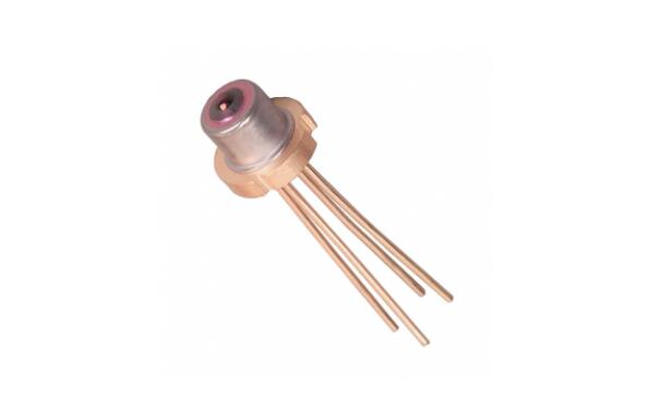
Detection of laser diode
A. According to the method of detecting the forward and reverse resistance of ordinary diodes, the pin arrangement order of laser diodes can be determined. However, it should be noted that the forward voltage drop of the laser diode is larger than that of the ordinary diode, so when detecting the forward resistance, the pointer of the multimeter just deflects slightly to the right.
Detection of low power crystal diode
A. Discrimination of positive and negative electrodes
(a) Observe the symbol mark on the housing. The symbol of diode is usually marked on the shell of diode. One end with triangular arrow is positive and the other end is negative.
(b) Observe the color dots on the housing. The shell of the point contact diode is usually marked with polar color dots (white or red). Generally, the end marked with a color dot is the positive pole. Other diodes are marked with a colored ring, and one end of the colored ring is a negative electrode.
(c) Subject to a measurement with a small resistance value, the end connected with the black probe is the positive electrode, and the end connected with the red probe is the negative electrode.
(d) Observe the diode housing, with a silver band, and one end is the negative pole.
B. Detect the maximum reverse breakdown voltage. For alternating current, because it changes constantly, the maximum reverse working voltage is the AC peak voltage borne by the diode.
Detect bidirectional trigger diode
Place the multimeter in the corresponding DC voltage range. The test voltage is provided by a megger. During the test, shake the megger and measure the VBR value in the same way. Finally, VBO and VBR are compared. The smaller the absolute difference between them, the better the symmetry of the measured bidirectional trigger diode.

Detection of transient voltage suppression diode (TVS)
A. Use a multimeter to measure the quality of the tube. For single pole TVs, the forward and reverse resistance can be measured according to the method of measuring ordinary diodes. Generally, the forward resistance is 4K & omega; The reverse resistance is infinite.
For TVs with two-way polarity, the resistance between the two pins measured by arbitrarily changing the red and black probes should be infinite. Otherwise, it indicates that the performance of the tube is poor or damaged.
Detection of high frequency varistor diode
The difference in appearance between positive and negative high-frequency varistor diodes and ordinary diodes is that their color code colors are different. The color code color of ordinary diodes is generally black, while the color code color of high-frequency varistor diodes is light. Its polarity law is similar to that of ordinary diodes, that is, one end with green ring is negative and one end without green ring is positive.
Detection of varactor
How to adjust the red and black leads of the multimeter for measurement, the resistance between the two pins of the varactor should be infinite. If the pointer of the multimeter swings slightly to the right or the resistance value is zero during the measurement, it indicates that the measured varactor has leakage fault or has broken down.
The above is the whole content of sharing experience in electronic component testing: judging the quality of various diodes. Learning to correctly detect electronic components and judge the quality of diodes is also a skill that electronic maintenance personnel must master. I hope it will be helpful to everyone's work.


 Weixin Service

 DouYin
 KuaiShou


