Description:
With the widespread use of electronic mobile products and the rise of the Internet of Things/Telematics, a large number of electronic components are applied in vehicles, with printed circuit boards (PCBs) being critical components. Besides the IPC-6012DA validation specification set by the international industry standard IPC - Association Connecting Electronics Industries for automotive PCBs, each automaker and Tier 1 automotive component supplier has their own PCB validation projects to ensure the produced products meet high reliability requirements.
Failure Description:
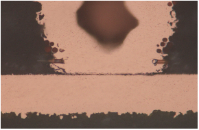
1.Connectivity abnormalities: The most common connectivity abnormalities are seen in broken plated through-holes (Figure 1) or blind vias (Figure 2), buried holes fracture causing electrical abnormalities due to circuit interruptions.
Figure 1: Plated Through Hole Barrel Cracks/Barrel Fatigue
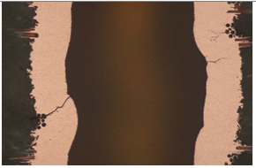
Figure 2: Blind Via Bottom Crack
These abnormalities can be verified by thermal shock tests, which subject the circuit boards to rapid temperature changes under defined test conditions and time to ensure that there are no significant changes in conductivity that exceed the target limits. Besides temperature variations, automotive PCB verification also introduces current to simulate operational conditions for a more stringent testing environment.
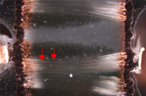
2.Insulation abnormalities: Insulation abnormalities are commonly caused by poor surface insulation or process/material anomalies, resulting in decreased insulation resistance and poor insulation, or even severe electrical abnormalities such as short circuits (Figure 3 and Figure 4).
Figure 3: Insulation Abnormalities between Surface Traces
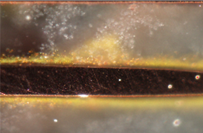
Figure 4: Fiberglass Filament Conduction between Holes
The most common acceleration factors for verifying insulation anomalies are temperature, humidity, and bias. Regardless of the testing conditions, the purpose is to validate the insulation resistance value of automotive PCBs at specified conditions and determine at what level the resistance value drop is considered abnormal. Additionally, the testing duration required for failure to equal the actual lifespan is determined. Each automotive component supplier will have corresponding specifications and methods. Adhering to these standards is crucial to ensure that one's products and process capabilities meet high reliability requirements.
3.Delamination abnormalities: The transition to lead-free assembly of automotive PCBs has been relatively slow but is now a necessity due to environmental considerations. Delamination issues encountered with automotive PCBs are similar to those with general PCBs. Therefore, the materials and processes used in automotive PCBs must be adjusted to ensure high reliability.
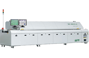
Solder reflow simulation equipment
SAT analysis of delamination abnormalities
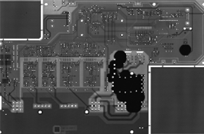
To verify the heat resistance of printed circuit boards, solder reflow simulation testing can be used. Key parameters include the temperature curve of the solder reflow furnace corresponding to the actual board temperature. These temperature requirements can reference international standards such as IPC and IEC, or the PCB validation requirements provided by automotive electronics suppliers. In addition to meeting the specifications for the solder reflow furnace equipment, another focus is the inspection method after the solder reflow simulation. Non-destructive inspection methods such as visual inspection and SAT (Scanning Acoustic Microscopy) can be used to detect abnormal locations. Destructive analysis (microsection analysis) is then performed to identify the root cause of the problems, allowing PCB suppliers to make improvements.


 Weixin Service

 DouYin
 KuaiShou


